Selection Guide:
When designing or selecting a swage spacer for your electronic hardware application, first decide whether a swage spacer or swage standoff will be best for your project. Then use the below guide to help you find the right swage size from the different options available.

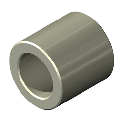
Swage Spacers
The Inner Diameters (ID) on a swage spacer are unthreaded and designed so a male thread can pass through without interference. This type of fit is called a clearance fit and why the ID can also be referred to as a “Clearance Hole”.

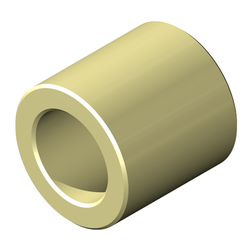
Swage Standoffs
Swage Standoffs are readily available in all common threads, in both inch and metric sizing. Swage Standoffs come with female threads on both ends of the part, with the Swage Shank being unthreaded. This allows for a screw or male standoff to be installed into either side. In shorter lengths, the thread will go through the entire part. Longer length standoffs are threaded to a minimum thread depth on each end.
Step 1 - Swage Length
As the swage end will be pressed onto the board, the proper swage length is critical to obtain the desired fit. Different lengths are provided for all off the common circuit board thicknesses.
| Panel Thickness (inch) | Lyn-Tron Code | Shank Length (±.003) |
|---|---|---|
| 1/64" | AA | 0.037" |
| 1/32" | A | 0.075" |
| 1/16" | B | 0.105" |
| 3/32" | C | 0.135" |
| 1/8" | D | 0.165" |
| 3/16" | E | 0.230" |
| 1/4" | F | 0.290" |
| 1/32" | H | 0.062" |
| 1/16" | I | 0.094" |
| 3/32" | J | 0.125" |
| 1/8" | K | 0.156" |
| 3/16" | L | 0.219" |
| 1/4" | M | 0.281" |
| Panel Thickness (mm) | Lyn-Tron Code | Shank Length (±.008) |
|---|---|---|
| 0.8mm | A | 1.9mm |
| 1.6mm | B | 2.7mm |
| 2.4mm | C | 3.4mm |
| 3.2mm | D | 4.2mm |
| 4.8mm | E | 5.8mm |
| 6.4mm | F | 7.4mm |
Step 2 - Swage Diameter
As the swage end will be pressed onto the board, the proper swage length is critical to obtain the desired fit. Different lengths are provided for all off the common circuit board thicknesses.
Step 3 - Inner Diameter (ID)
The Inside Diameter available will always be equal to, or slightly larger than your Spacer’s Clearance Hole or Swage Standoff’s Thread Size. This will allow the screw or male standoff end to pass through the spacer and the swage section without interference.
| Screw Size | Lyn-Tron ID Code | Clearance Hole Range (Inch) |
|---|---|---|
| #0 | 00 | 0.062"-0.072" |
| #2 | 02 | 0.088"-0.098" |
| #4 | 04 | 0.114"-0.124" |
| #6 | 06 | 0.140"-0.150" |
| #8 | 08 | 0.166"-0.176" |
| #10 | 10 | 0.192"-0.202" |
| #12 | 12 | 0.218"-0.228" |
| 1/4" | 25 | 0.252"-0.262" |
| 5/16" | 31 | 0.315"-0.325" |
| 3/8" | 38 | 0.377"-0.387" |
| Screw Size | Lyn-Tron ID Code | Clearance Hole Range (Metric) |
|---|---|---|
| M1.6 | 16 | 1.67mm-1.93mm |
| M2 | 20 | 2.07mm-2.33mm |
| M2.5 | 25 | 2.57mm-2.83mm |
| M3 | 30 | 3.07mm-3.33mm |
| M3.5 | 35 | 3.57mm-3.83mm |
| M4 | 40 | 4.07mm-4.33mm |
| M5 | 50 | 5.17mm-5.43mm |
| M6 | 60 | 6.17mm-6.43mm |
| M8 | 80 | 8.37mm-8.63mm |
Step 4 - Outer Diameter (OD)
A swage spacer or standoff will be a thru-hole component of the circuit board. The drill size you use to create the hole in the circuit board will correspond to a similar sized swage outside diameter. This will create a clearance fit, but once swaged your standoff will be held firmly in place. Some twisting should be expected under heavy torq, but super-torq standoff’s should be chose to minimize this further.
| Outside Diameter | Tolerance | |
|---|---|---|
| Inch | 1/8" (0.125") - 3/8" (0.375") | ±.005 |
| Metric | 4.5mm - 10mm | ±.13 |
Step 5 - Material & Plating Options
When deciding on a material and plating/finish, there are many properties that can be considered. The most common ones include corrosion and rust resistance, magnetism, electrical conductivity, strength to weight properties, color, and cost. Review the chart below to see which standard material has the right properties for your application’s environment.
| Materials | Corrosion Resistance | Magnetic | Electrical Conductor | Strength to Weight | Color | Plates |
|---|---|---|---|---|---|---|
| Stainless Steel | High | Slightly | Yes - Poor | Above Average | Grey | Available |
| Steel | Low | Strongly | Yes - Poor | Average | Grey | Available |
| Aluminum | Average | No | Yes - Average | Very Above Average | Grey | Available |
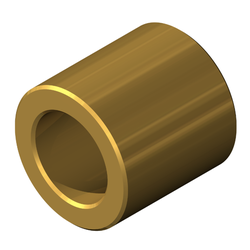
| Brass | High | No | Yes - Below Average | Average | Yellow | Available |
| Nylon | High | No | No | Average | White and can be dyed to other colors | No |
Installation Instructions
- Insert body of the Swage Spacer or Standoff into the Anvil.
- Install the Swage Shank through the previously drilled hole in the circuit board.
- Using an Arbor Press or other similar tool, put the Punch onto the Swage Shank.
- Push down on the Swage Shank until it rolls over onto the board.
Have a Question About Precision Shoulder Screws?
Electronic components are unique and guides can’t always answer everything. Please fill out this form and we will get right back to you.